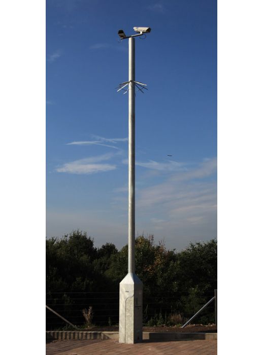
Tilt-Over CCTV Column (TCTO)
The TC range naturally evolved into the TCTO range of tilt-over columns, for use within city centre and urban schemes. The added bonus of maintenance at ground level make this a popular and safe first choice where access for maintenance is of concern. The 400 square cabinet remains the mainstay of this range, with the 325 cabinet option readily available. The sturdy, proven design, along with many versatile features, keep it at the forefront of CCTV urban furniture with the added bonus of tiltability.
General Specification
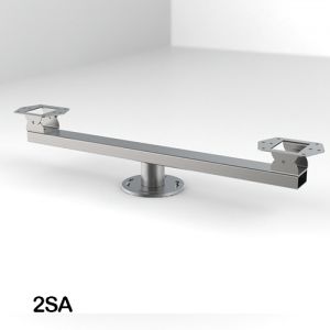
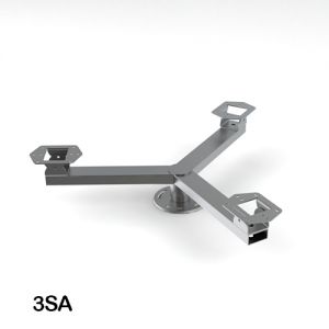
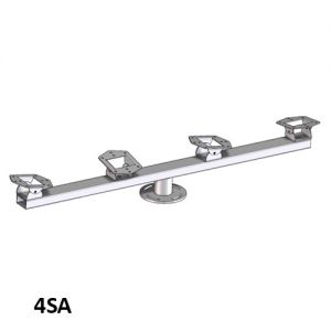
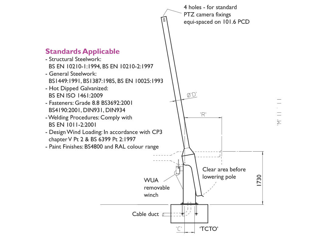
- Standard pan and tilt fixing of 101.6 PCD.
- Built in cable entry and exit points.
- Compatible with WEC adaptors, accessories and anti climbs.
- Flange mounted TC type root.
- Pocket type roots available for restricted foundation locations.
- Loadings up to 25 kg.
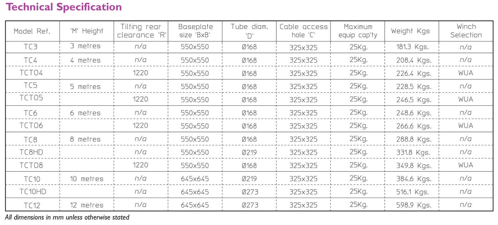
- A large variety of standard heights from 3 up to 10 metres*
*See Technical Sheet for further information, please note the heights specified are nominal and may vary.
Design Features
- The versatile column for urban CCTV schemes.
- The tilt over column enables safe camera maintenance at ground level.
- Integral lockable cabinet base for housing telemetry, fibre optics, spurs etc.
- Excellent stability characteristics ensures minimal camera movement.
- Recommended for installation in high profile and public places.
- Desirable columns where aesthetics are of importance.
- Totally concealed cable management facility.
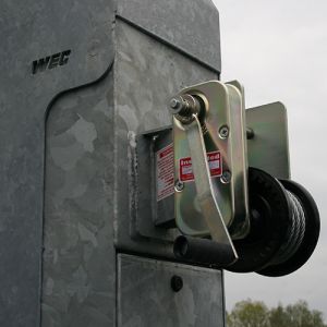
- A transferable winch allows multi site-servicing and leaves installation tamper proof.
- High security and VAULT door options for high risk areas.
- Hot dipped galvanised finish for maximum weather protection and low maintenance requirements.
- Custom and bespoke versions tailored to the customer's requirements.
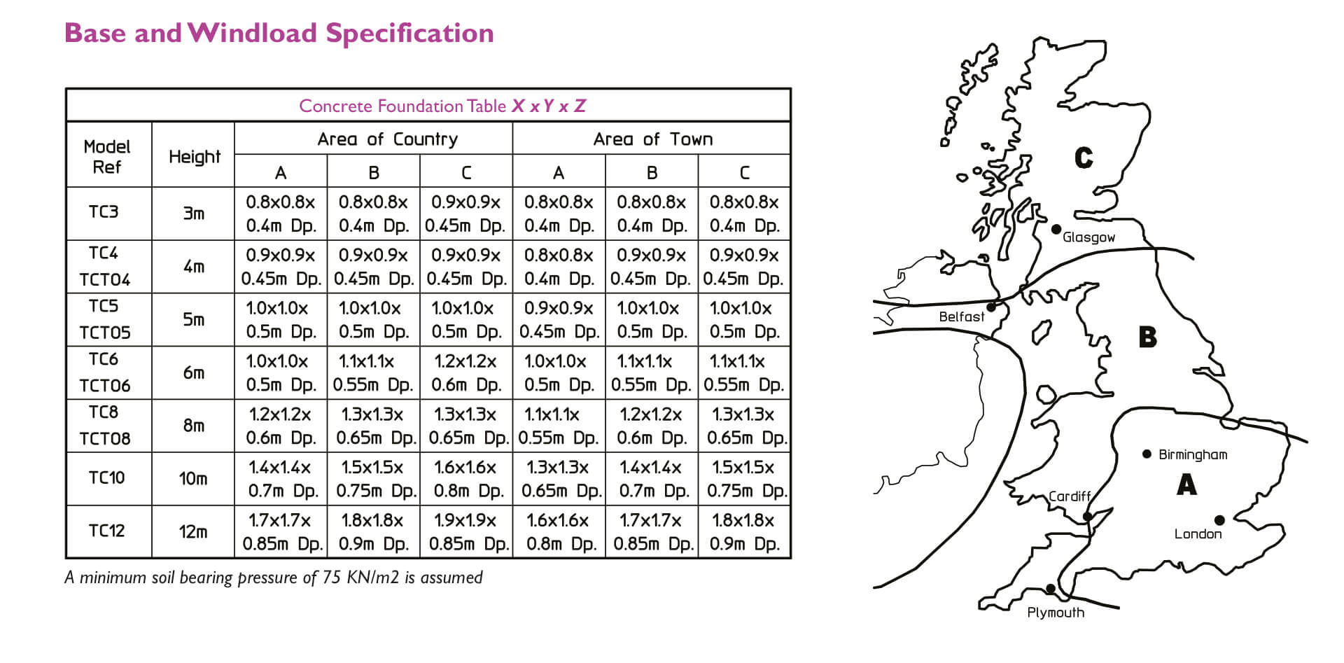
1. From the map, select location of installation
2. Excavate as per recommended area and depth
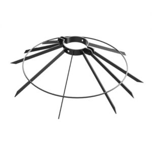
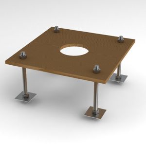
3. Assemble root base as shown in fig. 1
4. Insert root base into the hole ensuring that it is level and that the four studs protrude 60-70mm above the concrete foundation
5. Fit the cable duct if routing via the interior of the column. A plastic pipe of approximately 100mm outside diameter is recommended for this. Ensure this protrudes through the template by 50mm minimum.
6. Pour concrete ensuring that it is a mix of C35 to table 6 BS 8110 and then tamp down well
7. Fit the setting template over the four protruding studs, double-checking that they are level and that clear access can be gained to the cable duct if it is being used
8. Leave the concrete to cure for a minumum of 72 hours prior to attempting to erect the column
9. When fitting the column, ensure that the concrete base is in complete contact with the underside of the column and grout accordingly.
10. When the column has been fitted, protect the studs with a suitable protective coating. Denzo tape or similar is recommend for this